
Buchka Wasted Spark Board Installation Instructions
by Karl Buchka, Chris Floren
Below are instructions for the installation of the LH2.4 / EZK wasted spark boards. We're focusing pretty heavily on the installation of the board itself. There are far too many combinations of ignition modules and coils to provide comprehensive instructions on that part of the project. The disclaimer is basically this: Some brain power required, some assembly required, batteries not included.
A list of handy references is included at the bottom of this page. We will continue to update this and add more information.
Your shipment should include the following items:
- 1x Wasted spark conversion PCB
- 1x Mounting screw
- 1x Plastic mounting washer
1. Directions for installation
The conversion board has been designed to be mounted inside the stock Bosch EZK box found in later rear-wheel-drive Volvos equipped with LH2.4 engine management and EZK ignition. On 240s the EZK control box is mounted on the front right corner of the firewall, right above the foot well. On 740s and 940s it is mounted under the dash, above the throttle pedal.
Remove the EZK box from the car, and using a Torx screwdriver, remove the four screws on the end of the case and the three screws around the connector. This should allow you to open the housing of the EZK box and gain access to the circuit board itself.
The conversion board has 8 labeled solder pads. The four pads labeled "5V", "GND", "Spk", and "VR" need to be tied to the four labeled points on the EZK board [fig 1]. "VR" goes to pin 7 of the LM2903 IC. If you tin the leg of the IC you can easily attach a wire to it. The "Spk" pin is actually intended for pin 16 of the main connector, but we find soldering it to the indicated resistor leg makes for a cleaner installation. If you want to solder your wire directly onto pin 16, feel free to do so. The 5V and GND supply points should be self explanatory. Make sure you don't reverse them. That would be bad. We recommend potting all the wire-to-PCB connections with hot glue to secure the wires from vibration.
The two pins labeled 1-4 and 2-3 are the new logic-level spark outputs. They need to come out of the box and go to the proper pins on your power stage/coil. *Important note: on the current batch of boards, the 1-4 and 2-3 pins were reversed in programming. This means you will need to connect "1-4" to cylinders 2 & 3, and "2-3" to cylinders 1 & 4.* If your car is not equipped with EGR you can piggyback on those pins, or you can just drill a hole in the box to pass the wires through, or install a new dedicated connector of your choice.
Using the supplied screw and mounting washer, attach the board to the body of the main EZK connector [see Figure 1]. Depending on clearance to the housing, it may be necessary to mount the board in an inverted fashion.
We recommend the use Bosch Motorsport 2x2 wasted spark ignition coil (part #: 0 221 503 407, available from CFloMoTo here). This is the only ignition coil we have found with documented dwell characteristics that match the built-in EZK dwell. The stock ignition module has one output stage, but since the wasted spark system requires two outputs you can either install an additional stock ignition module or replace it with a multi-channel equivalent (eg. Bosch 0 227 100 203, Volvo 960, or Hüco equivalent available here).
A sample wiring diagram is shown in Figure 2. An example of the wasted spark board installed in the EZK box is shown in Figure 3.
It is important to note that these parts are simply suggestions. You are free to use any suitable combination of ignition modules and coils.

Figure 1. Preferred connection points inside the EZK box. Note the multiple 5v and Ground suggestions.

Figure 2. Suggested ignition module wiring.

Figure 3. Example of wasted spark board installed in EZK box (note small green PCB in bottom right corner, held in place by the supplied screw and plastic mounting washer).
Tips for wiring up the Buchka Wasted Spark board to your EZK:
- You will need to drill a hole in your outer EZK case for a 2-pin or 4-pin connector to add the new wires. 2 pin for wasted spark only, 4 pin is needed if you also want launch control.
- We recommend a bulkhead style connector with nuts that hold it in place. Exact position will depend on available space in your car and on your own personal preference.
- For wire gage, we recommend around 20-22 AWG (between 0.50 to 0.34 mm^2), both internally and externally. The wires do not handle very much current, so these thinner gages are OK. If you go too thick it becomes difficult to get everything routed nicely inside the EZK.
- Make sure wherever you drill the hole for your bulkhead connector is over an open space and does not interfere with anything inside the EZK.
- You will want to run the output wires through the hole after soldering to the board but before attaching the connector, with the box disassembled on your bench. It's a little bit fiddly but not difficult if you take your time.
- For soldering, use a low-power soldering iron with a small tip, or one that has adjustable power output. The solder pads on the board don't need much heat at all to melt so be careful and go slow. It is easy to melt too much!
- After everything is soldered up we recommend testing out the conversion in the car, making sure it all works before finalizing the WS board installation in the EZK.
- After verification that the wasted spark conversion is fully functional, we recommend opening the EZK again and using hot glue to "pot" or reinforce the newly soldered joints on the WS board and the EZK board. This helps keep everything solid and reduce the risk of solder cracking from vibration. Potting also helps with strain relief.
- We suggest quality heat shrink for the output wires and for the new harness you'll need to build between your coil(s) and power stage.
2. Adjustable hard-cut rev limit (experimental)
NOTE: This feature is considered experimental. This means we don't guarantee it will work well, or even at all. It means use at your own risk and we are not liable for any damage caused by its operation. Basically don't be an idiot.
Your wasted spark conversion also comes with an experimental hard-cut rev limit/launch control/flat shift feature. In essence it allows you to hold the engine at any rpm, even whilst applying full throttle. This should enable more consistent launches from a standing start. It is important to note that this is not an "anti-lag" function since ignition timing is not being retarded.
Recommended wiring diagrams for the arm and set features are shown in Figure 4. The dash-mounted set switch should ideally be momentary and the clutch switch must close to ground as the clutch is depressed.
It is important to note that the launch control feature will be completely disabled by simply not connecting anything to the set and arm pads.

Figure 4. Suggested launch control wiring.
3. Tachometer options
Depending on how you have the system wired, there are a couple of different ways to drive the tachometer.
The first (and arguably easier) method works if you have left the stock ignition power stage and wiring intact. Simply move any wires currently connected to the stock coil's two spade terminals to the "85" and "86" terminals of an automotive relay. To keep the relay from clicking you should open the body of the relay and remove the contactor assembly. An example of this is shown in Figure 5.
Alternatively, if you have chosen to remove or modify the stock wiring, then driving the tachometer can most easily be done by building a circuit similar to the one listed in the MS-Extra manual under "Option for High Voltage tacho" (http://msextra.com/doc/ms1extra/MS_E...l.htm#tachoout). The base of the transistor should be connected to the stock EZK spark output pin. Note that this solution uses the same modified automotive relay as mentioned earlier.

Figure 5. Example automotive relay modified to act as a tachometer driver.
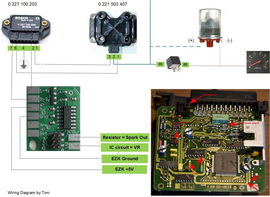
Figure 6. Here's a nice wiring diagram for one suggested setup. This was made by one of our customers, Toni.
4. References
Compatible EZK Boxes:
We think it may be possible that all EZ116K boxes are compatible with the Buchka Wasted Spark conversion, but that has not been independently verified. We do know that the following list of EZK boxes will work. If your EZK box is a silverish/goldish color (not black) then it is a chippable box, with a separate daughter board for the ignition calibration chip. EZ116K is found on naturally aspirated 8-valve redblocks, turbo 8-valve redblocks, and 16-valve NA redblocks - therefore wasted spark is compatible with any of these, as long as EZ116K (as found with LH2.4) is present.
The last 3 digits of the Bosch part number are the common reference number for these.
All are in the format of "0 227 400 xxx" with the xxx representing the last 3 digits below:
146
148
152
169
207
214
219
Chippable "gold" boxes include:
147
207
208
209
219
Turbobricks Forum Links: